Gate Drive Transformers for IGBTs
High Power Density Meets High Insulations Strength
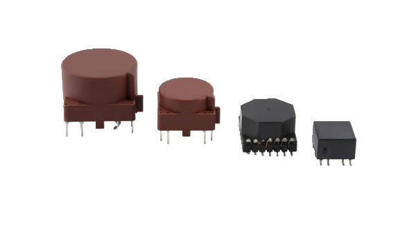
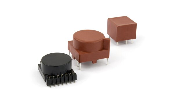
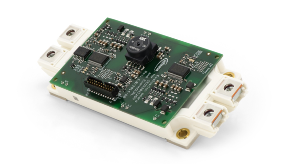
Gate drive transformers for IGBT are the key element in the driver circuit supplying the necessary power for switching and maintaining safe galvanic separation between the intermediate circuit and the low voltage control side.
By using nanocrystalline VITROPERM® as core material, VACUUMSCHMELZE gate drive transformers combine high power density with high insulations strengths.
Benefits:
- Reinforced insulation
-
Low coupling capacitance
-
Low leakage inductance
-
Large voltage-time area in compact designs
The selection of a suitable Gate Drive Transformer typically starts with the number of windings and transmission ratio: The required number of windings is usually given by the circuit topology while the transmission ratio is determined by the ratio between the input and output voltage.
The voltage-time area of the transformer is an important parameter as it basically couples the electric requirements with the internal magnetics. The requirements are calculated by considering the input voltage and switching frequency.
In unipolar operation half of the hysteresis loop is used, so ΔB can be considered as 0.9 T if VITROPERM® is used as core material. Accordingly, the required iron cross section AFe can stay small.
Furthermore, the insulation requirements have to be considered: They are usually related to the recurring peak voltages in the system. The parasitic parameters must also be taken into account: Low leakage inductance guarantees steep control pulses, while low coupling capacitance avoids misfirings of the IGBT. Depending on the winding design, usually a compromise has to be found between both parameters.
Downloads
Related Products

Energy Conversion
No matter if you are looking for state-of-the-art current transformers, gate drive transformers or materials as a superior basis for your own components. With our vertical integration we cover various forms of supply to support your business.

Power Electronics
Our power electronics solutions are comprised of current measurement devices such as closed loop current sensors and differential current sensors as well as filter cores and common mode chokes for EMC applications.

Electric Vehicle Charging
Our portfolio comprises inductive components and electrical safety devices for all charging modes and meets the requirements of various standards such as IEC 62752 or UL2231.
Contact Us Think Global - Act Local
We are looking forward to support you.
